What is Cavitation in Pumps, How to Avoid It.
⏱️ Estimated Reading Time: 07 min
🗓️ Last Updated: 29 August 2025
Cavitation is a destructive phenomenon in pumps that occurs when the liquid pressure drops below its vapor pressure, leading to the formation of vapor bubbles (also called cavities) within the fluid. These bubbles collapse suddenly when they move into higher-pressure regions, producing intense shockwaves that can severely damage pump components, reduce hydraulic efficiency, and ultimately lead to premature failure.
Where Cavitation Occurs
Leading Edge of Impeller: Cavitation typically begins at the leading edge of the impeller blades near the suction eye (pump inlet). Here, the liquid is accelerated into the impeller channels. The combination of fluid velocity and impeller design can create regions of reduced pressure, making them susceptible to vapor formation.
Suction Side of Impeller: Cavitation can also occur along the suction side of the impeller where pressure gradients are highest. The sudden change in velocity as fluid enters the impeller vanes lowers static pressure. If the inlet pressure is insufficient (low Net Positive Suction Head, or NPSH), vapor bubbles form.
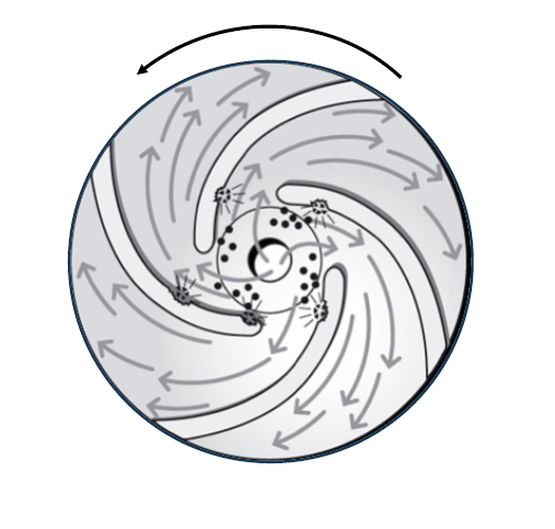
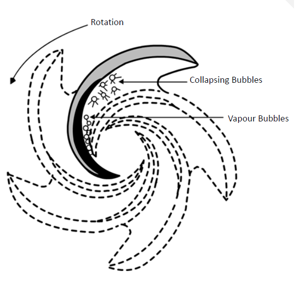
How Cavitation Happens
As fluid enters the pump impeller, high velocities or restricted flow can cause the local pressure to drop below the fluid’s vapor pressure. This results in the formation of vapor bubbles. When these bubbles travel into regions of higher pressure, such as further along the impeller blades, they implode violently. The energy released during this implosion can pit and erode metal surfaces, compromising pump integrity.
Types of Cavitation
1. Classic (Vapor) Cavitation
Cause: Occurs when the pressure at the pump inlet drops below the fluid’s vapor pressure, causing vapor bubbles to form.
Symptoms: Loud cracking or popping noises, pitting damage on the suction side of impeller blades, and high vibration at 3× the blade-pass frequency.
Effects: Reduced pump efficiency, accelerated wear, and potential impeller failure.
Solutions: Increase NPSHa (elevate fluid supply, shorten suction piping), reduce pump speed, or trim the impeller diameter.
2. Internal Recirculation Cavitation
Cause: Results from operating the pump at very low flow rates (below 50% of BEP), causing fluid to recirculate violently inside the impeller.
Symptoms: Distinct damage on the *pressure side* of impeller blades (unlike suction-side damage in vapor cavitation) and high-frequency vibration.
Effects: Premature impeller and seal failure due to erratic hydraulic forces.
Solutions: Install an automatic recirculation valve (ARC) or avoid prolonged low-flow operation.
3. Discharge Cavitation
Cause: Triggered by excessively high discharge pressure, which restricts flow and creates vapor bubbles at the impeller outlet.
Symptoms: Fractured or eroded impeller vanes, frequent seal/bearing failures, and noise near the discharge port.
Effects: Catastrophic impeller damage and system instability.
Solutions: Open discharge valves fully, check for clogged filters, or reduce system pressure.
4. Air Aspiration Cavitation
Cause: Air enters the suction line through leaks (e.g., loose flanges) or vortexing in the supply tank.
Symptoms: Unstable flow/pressure readings, foamy discharge fluid, and sporadic noise.
Effects: Reduced pump performance and air-induced corrosion.
Solutions: Ensure proper submergence (5× pipe diameter below fluid level) and pressure-test suction piping.
5. Turbulence Cavitation
Cause: Poor suction piping design (e.g., sharp elbows, undersized pipes) disrupts smooth flow.
Symptoms: Localized pitting near pipe fittings and noise that fluctuates with flow rate.
Effects: Erosion in pipes and impellers, reduced efficiency.
Solutions: Use straight suction pipes (5–10× diameter length), replace 90° elbows with long-radius bends.
How to Prevent Cavitation
Given below are some actionable solutions to prevent all major cavitation types through proper system design, pump selection, and operational best practices.
Prevention Strategies for Different Cavitation Types
1. Classic (Vapor) Cavitation Prevention
To prevent vapor cavitation caused by insufficient NPSHa, elevate the liquid supply tank by 1-2 meters to increase static head pressure. Alternatively, replace long suction pipes with wider-diameter piping (minimum 1.5x pump inlet size) to reduce friction losses that contribute to pressure drops.
For high-temperature applications, install a booster pump upstream to maintain adequate suction pressure, particularly when handling volatile fluids like LPG or hot water above 80°C where vapor pressure rises exponentially.
2. Internal Recirculation Cavitation Mitigation
Install an automatic recirculation valve (ARC) that maintains minimum flow rates above 50% of BEP, preventing reverse flow conditions that cause destructive recirculation. For variable load systems, implement a VFD-controlled bypass loop that modulates flow without throttling valves, ensuring stable operation across all demand scenarios.
3. Discharge Cavitation Control
Replace throttled discharge valves with automated control valves that maintain steady downstream pressure within 10% of design points. In high-pressure systems (>50 bar), install a pressure sustaining valve on the discharge header to prevent backflow-induced vaporization at the impeller periphery.
4. Air Aspiration Elimination
Design suction tanks with vortex breakers (cross-shaped baffles) positioned 30 cm below the minimum operating level to prevent air entrainment. For critical hydrocarbon services, specify dual mechanical seals with nitrogen barrier gas at 1.5x suction pressure to ensure zero air ingress.
5. Turbulence-Induced Cavitation Solutions
Redesign suction piping with 10x pipe diameter straight runs before the pump inlet, using computational fluid dynamics (CFD) to verify laminar flow (Re < 2300). Replace standard 90° elbows with 45° long-radius bends (centerline radius ≥ 3x pipe diameter) to minimize flow separation and localized pressure drops.
Advanced System Design Protocols
NPSH Optimization Framework
Calculate NPSHa using the modified Bernoulli equation:
NPSHa = P_suction + P_atm – P_vapor – h_friction
Maintain a safety margin of 1.5x NPSHr across the entire operating curve, verified through transient hydraulic modeling during system commissioning.
| NPSH Scenario | Optimal Pump Type | NPSH Advantage | Typical Applications |
|---|---|---|---|
| Very Low NPSHa (<2m) | Inducer-Equipped Centrifugal | NPSHr as low as 1.2m | Hot condensate, LPG transfer |
| Low NPSHa (2-5m) | Double-Suction Centrifugal | 30% lower NPSHr vs single-suction | Boiler feed, high-temp water |
| Moderate NPSHa (5-10m) | Axial Flow Split-Case | Stable operation at 70-110% BEP | Large volume water supply |
| High Vapor Pressure Fluids | Vertical Can Pump | Submerged impeller eliminates suction lift | Refrigerants, volatile hydrocarbons |
| Variable NPSHa Conditions | VFD-Controlled Multistage | Auto-adjusts speed to maintain NPSH margin | Solar thermal systems, tidal pumps |
Advanced Predictive Maintenance Techniques for Cavitation Prevention
Cavitation damage often develops gradually before catastrophic failure occurs. Implementing predictive maintenance (PdM) allows early detection and intervention, reducing downtime and repair costs. Below are the most effective techniques:
1. Vibration Analysis (ISO 10816-7 Standards)
- Cavitation generates high-frequency vibrations at 3× blade pass frequency (BPF) and harmonics.
- Accelerometers mounted on pump bearings detect these vibrations.
Implementation:
- Use wireless sensors (e.g., Emerson CSI 9420) with cloud-based analytics.
- Set alarms at 80% of allowable vibration limits (per ISO 10816).
Case Study:
A chemical plant reduced unplanned downtime by 62% after installing vibration monitors on 40 critical pumps, detecting cavitation 4-6 months before failure.
2. Ultrasonic Cavitation Detection
- Cavitation bubble implosions emit ultrasonic frequencies (25-40 kHz).
- Ultrasonic transducers (e.g., UE Systems Ultraprobe) detect these signals.
Advantages Over Vibration Monitoring:
- Detects early-stage cavitation before vibration spikes occur.
- Works on low-speed pumps** (<600 RPM) where vibration analysis is less effective.
Installation Tips:
- Mount sensors on suction piping (not discharge).
- Baseline readings should be taken during normal operation.
3. NPSH Margin Real-Time Monitoring
Sensor Requirements:
- Pressure transmitters (suction/discharge) with ±0.1% accuracy.
- Temperature sensor for vapor pressure calculation.
Control Logic:
- If NPSHa/NPSHr < 1.3, trigger an alarm or auto-throttle pump speed.
- Integrate with PLC/DCS for automated responses.
Example:
A power plant uses MODBUS-enabled Rosemount 3051S transmitters to maintain NPSH margins >1.5x, eliminating cavitation in boiler feed pumps.
4. Motor Current Signature Analysis (MCSA)
- Cavitation modulates motor load, creating sideband frequencies around line frequency (50/60 Hz).
- Current sensors detect these anomalies.
Diagnostic Indicators:
| Fault | Frequency Pattern |
|---|---|
| Cavitation | Sidebands at ±BPF |
| Bearing Wear | Peaks at 1-3x RPM |
| Misalignment | 2x RPM (Radial), 1x RPM (Axial) |
| Unbalance | 1x RPM (Dominant Peak) |
Best For:
- Pumps without vibration access (e.g., sealed or submersible).
5. Infrared Thermography
Application:
- Cavitation causes localized temperature spikes in impeller zones.
- Thermal cameras (e.g., FLIR T540**) identify hot spots.
Limitations:
- Only effective for visible pump casings (not sealed designs).
- Requires baseline thermal profiles for comparison.
Related Content
Fans and Blowers
Explore page about Fans & Blowers, Types, Selction Criteria and Applications