ASME B16.5 Overview – Standard for Pipe Flanges and Flanged Fittings

ASME B16.5 is one of the most widely used piping standards in the oil & gas, chemical, power, and process industries. It standardizes the design of pipe flanges and flanged fittings for sizes NPS ½ through NPS 24, covering pressure classes 150 to 2500. By defining pressure-temperature ratings, dimensions, materials, tolerances, and testing requirements, it ensures global compatibility between piping systems, gaskets, and bolting assemblies.

Introduction

ASME B16.5 provides engineers with a standardized framework for designing and procuring pipe flanges and flanged fittings. This Standard specifies the pressure–temperature ratings, materials, dimensional requirements, tolerances, marking methods, and designation system for openings used in pipe flanges and flanged fittings. It also outlines the essential requirements and recommendations for flange bolting, gasket selection, and joint assembly.

Both SI (Metric) and U.S. Customary units are used throughout this Standard. However, bolt and bolt hole diameters are given exclusively in inch units. Each system of measurement is to be considered independently as a valid standard.

Scope of ASME B16.5

The scope defines what the standard covers and its limits:

  • Pipe Size Range: NPS ½″ to 24″ (larger flanges covered under ASME B16.47).
  • Flange Types: Weld Neck, Slip-On, Blind, Socket Weld, Threaded, Lap Joint, Ring-Type Joint.
  • Pressure Classes: 150, 300, 400, 600, 900, 1500, and 2500.
  • Materials: Carbon steel, stainless steel, alloy steel, nickel alloys, etc., as referenced in ASTM standards.
  • Applications: Process piping, refinery units, LNG facilities, offshore structures, boilers, and pressure vessels.

ASME B16.5 defines the specifications for pipe flanges and flanged fittings made from forged or cast materials. It also includes details for blind and reducing flanges, which may be manufactured using forged, cast, or plate materials. The standard provides essential guidelines for flange gaskets, bolting, and proper joint assembly to ensure safe and reliable piping connections.

ASME B16.5 is commonly used alongside other ASME standards, including the Boiler and Pressure Vessel Code and the B31 Piping Codes, as well as other parts of the ASME B16 series that cover various types of fittings and components.

Key Exclusions: Flanges larger than NPS 24" are covered under ASME B16.47 Series A & B. Furthermore, B16.5 is a component standard; it does not govern the overall piping system design, which falls under codes like ASME B31.3 (Process Piping).

Pressure-Temperature Ratings

ASME B16.5 provides tables listing the maximum allowable pressure at specific temperatures for each material group. Each flange is assigned a pressure class (150, 300, 600, etc.), which does not directly equal pressure (psi) but represents a range depending on material and temperature. A Class 300 flange does not mean good for 300 psi. As temperature increases, the allowable pressure rating decreases.

Description of the image

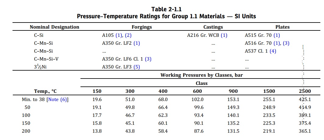
Pressure–Temperature Ratings for Group 1.1 Materials — SI Units (Source: ASME B16.5-2025)

Materials and Specifications

ASME B16.5 governs the materials used for flanges and flanged fittings by referencing established ASTM International standards. The standard provides a definitive list of approved materials, organized into groups to simplify pressure-temperature rating selection.

Permitted materials include forgings, castings, and plates that conform to the specified ASTM standards. Common material specifications referenced include;

  • Carbon Steel: ASTM A105, A350 LF2 (low-temp service)
  • Stainless Steel: ASTM A182 F304/F316
  • Alloy Steel: ASTM A182 F11, F22 (high temperature)
  • Nickel Alloys: ASTM B564 grades for corrosive/cryogenic service

A fundamental aspect of the standard is its Material Group system. Materials with similar mechanical properties are grouped together, and the all-important pressure-temperature ratings are assigned to these groups rather than to each individual material. This means that different material grades within the same group share an identical pressure-temperature rating table, ensuring consistency and simplifying the engineer's selection process.

Flange Types and Applications

Flange TypeDescriptionTypical Use
Weld Neck (WN)Long tapered hub, butt-weldedHigh pressure, high temperature critical service
Slip-On (SO)Pipe slides into bore, fillet weldedLow-pressure water lines, utilities
Blind (BL)Solid plate, no boreClosing ends, hydrostatic testing
Socket Weld (SW)Pipe inserted into socket, fillet weldedSmall-bore, high-pressure lines
Threaded (THD)Internal threads, no weldingLow-pressure, maintenance-friendly
Lap Joint (LJ)Two-piece with stub endLines requiring frequent disassembly
Ring Type Joint (RTJ)Machined groove for metal gasketHigh-pressure, leak-critical services

Engineering Tip: Always match flange face (RF, FF, RTJ) with the correct gasket type. Using a flat gasket on an RTJ flange will cause leakage.

Dimensions and Tolerances

ASME B16.5 establishes definitive dimensional standards to ensure perfect flange interchangeability across global supply chains. The standard's comprehensive tables provide mandatory specifications for all critical measurements that govern flange manufacturing and assembly.

The dimensions cover fundamental characteristics including outside diameter, thickness, and bore size, which define the flange's basic envelope. For connection integrity, the standard specifies bolt circle diameter along with the number, size, and threading requirements for bolt holes. For weld neck flanges, additional hub dimensions ensure proper structural transition to the piping system. The standard also meticulously defines facing details, including raised face height and diameter, plus complete specifications for Ring-Type Joint groove geometry.

These dimensional requirements are coupled with explicit machining tolerances that control facing flatness, bolt hole alignment, and flange perpendicularity. This ensures components from any manufacturer will align correctly and form reliable, leak-tight connections when properly assembled with appropriate gaskets and bolting.

Description of the image

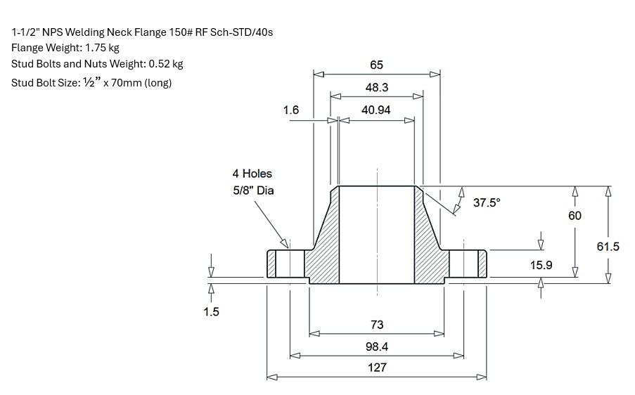
Standard Welding Neck Flange Dimensions as per ASME B16.5-2020

Marking, Testing, and Quality Assurance

ASME B16.5 enforces a rigorous framework for quality assurance, ensuring every flange and flanged fitting meets strict standards for safety, performance, and traceability. This multi-layered approach provides engineers and inspectors with verifiable confidence in component integrity.

Identification and Traceability

Permanent markings are mandatory and serve as a flange's unique fingerprint. Each component must be legibly stamped with the following:

  • Size and Pressure Class: The Nominal Pipe Size (NPS) and pressure class (e.g., 150, 300, 600).
  • Material Specification: The ASTM material grade (e.g., A105, A182 F316)
  • Manufacturer Identification: The manufacturer's name or trademark
  • Heat Number: A critical code that provides full traceability to the specific material melt and associated chemical and mechanical test reports.
  • Conformance Designation: The marking "B16.5" to confirm manufacture in accordance with this standard.

Engineering Tip: During inspection, always verify flange markings match the material test certificate (MTC) before installation.

Hydrostatic Testing

To validate pressure integrity, the standard requires hydrostatic testing. Flanged fittings are pressure tested at a minimum of 1.5 times the rated pressure at 100°F (38°C). This test verifies the soundness of the pressure-containing walls and confirms the fitting can safely withstand pressures beyond its normal operating range without leakage or failure.

Manufacturer Quality Control

Manufacturers are required to maintain a quality control system that complies with ASME and ASTM requirements, encompassing verification of chemical composition, confirmation of mechanical properties like tensile strength and hardness, and strict adherence to documented heat treatment processes. This comprehensive system of material verification and process control forms a robust foundation for mechanical integrity, ensuring global interchangeability and leak-free performance in critical piping systems.

Integration with Other Codes

ASME B16.5 flanges are not standalone — they integrate with:

  • ASME B31.3 (Process Piping): For piping design, stresses, and flexibility.
  • ASME Section VIII Div. 1 (Pressure Vessels): For vessel nozzle connections.
  • API 6A / API 607: For oilfield and fire-safe applications.

Engineering Tip: If your project involves pressure vessels, always check compatibility between B16.5 flange rating and vessel design pressure as per ASME VIII.

Conclusion

ASME B16.5 provides engineers with a standardized, reliable framework for designing and procuring flanges and flanged fittings. By carefully selecting the correct pressure class, material, and flange type, engineers can ensure safe and leak-free operation across a wide range of industries. When integrated with ASME piping and pressure vessel codes, B16.5 becomes a critical reference point for mechanical integrity in oil & gas, power, and chemical plants.

For precise design and manufacturing, always consult the official ASME B16.5 standard. Using these reference tables and diagrams improves design speed and reduces errors while staying compliant with industry standards.

Related Content

Learn more about related piping standards: ASME B16.9 – Buttwelding Fittings.
Understand pipe material specifications in detail: Piping Material Specifications.