What is a Distributed Control System (DCS)?
Imagine managing a complex industrial plant; like an oil refinery or a power generation facility, where a single malfunction can have significant consequences. Centralizing all control in one location would be inefficient and risky. This is the problem a Distributed Control System (DCS) solves.
A Distributed Control System (DCS) is an advanced automated control system used extensively in industrial and process plants. Unlike centralized control systems, a DCS distributes control functions across multiple autonomous controllers within the plant, allowing localized control while maintaining centralized monitoring and coordination.
Key Components of a DCS
A DCS is more than just controllers; it’s an integrated ecosystem. Here are its core components:
Engineering Workstation (EWS): The “brain trust” of the system. Engineers use this to design, configure, and troubleshoot the control logic and operator interfaces.
Operator Workstation (OWS): The “mission control” center. This Human-Machine Interface (HMI) allows operators to monitor the entire process, view real-time data, acknowledge alarms, and make manual adjustments.
Controllers: The “local brains” of the operation. These ruggedized computers are placed close to the equipment they control, executing control algorithms (like PID loops) in real-time.
Input/Output (I/O) Modules: The “senses and hands” of the system. They act as the bridge, converting analog signals from field devices (e.g., 4-20 mA) into digital data for the controllers, and vice-versa.
Communication Network: The “nervous system.” High-speed, often redundant networks (like Ethernet or Fieldbus) connect all components, ensuring timely and deterministic data flow.
Field Devices: The “fingertips” in the field. This includes sensors (e.g., pressure transmitters, temperature sensors) that measure the process and actuators (e.g., control valves, motor starters) that carry out commands.
How the DCS System Works (From Sensor to Screen)
To understand how these components work together, let’s follow a pressure signal’s path through the system:
Step 1: Measurement
A Pressure Transmitter in the field measures 50 PSI and converts it into a 12 mA electrical signal.
Step 2: Consolidation
Wires from this transmitter and other nearby instruments terminate at a Junction Box (JB), which groups signals for efficient routing to the control room via a single multi-core cable.
Step 3: Interface & Protection
The cable enters a Marshalling Cabinet. Here, field wires are neatly terminated, and the signal is conditioned and protected from power surges and electrical noise by isolators and surge protectors.
Step 4: Conversion
The signal reaches an Analog Input (AI) Card in the DCS rack. This card converts the 12 mA signal into a digital value the controller can understand (e.g., “50.0 PSI”).
Step 5: Decision
The DCS Controller receives this data. It runs a pre-programmed control algorithm (e.g., “If pressure > 60 PSI, trigger an alarm”). It decides to maintain the current valve position.
Step 6: Visualization & Storage
The live pressure value (50.0 PSI) is displayed on the Operator Workstation (HMI). Simultaneously, the Historian database records this data for future analysis, reporting, and optimization.
DCS vs. PLC vs. SCADA: Choosing the Right System
It’s common to confuse DCS with Programmable Logic Controllers (PLCs) and Supervisory Control and Data Acquisition (SCADA) systems. Here’s a clear comparison:
| Feature | Distributed Control System (DCS) | Programmable Logic Controller (PLC) | SCADA System |
|---|---|---|---|
| Primary Use | Continuous process control (e.g., refining, chemical) | Discrete/logic control (e.g., assembly lines, packaging) | Wide-area monitoring & control (e.g., pipelines, utilities) |
| Architecture | Distributed control with integrated oversight | Centralized or localized control | Supervisory layer over PLCs and RTUs |
| Focus | Process-oriented, holistic plant control | Machine-oriented, fast, repetitive tasks | Data acquisition, visualization, and remote control |
| Redundancy | Built-in at all levels (controller, network, etc.) | Optional, typically added for critical applications | Optional, often focused on servers and communications |
| Integration | Native integration of I/O, controllers, and HMI | Components from different vendors are often integrated | Designed to integrate disparate devices and protocols |
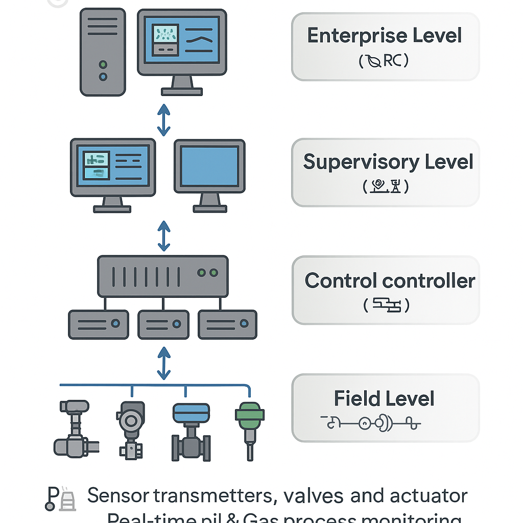
DCS Architecture
DCS follows a hierarchical structure with multiple layers:
- Field Level: Field instruments and actuators.
- Control Level: Distributed controllers with dedicated control logic.
- Supervisory Level: Operator and engineering stations with visualization and logging.
- Enterprise Level: Integration with management and ERP systems.
Communication in DCS: The Plant’s Nervous System
The communication network is the vital nervous system of a Distributed Control System. It must be deterministic to guarantee data delivery within a fixed time for real-time control, and redundant to provide immediate backup pathways, ensuring no single point of failure can halt the entire process.
Deterministic and Redundant Control Networks form the high-speed backbone of the DCS. These are typically industrial Ethernet networks that connect operator stations, engineering stations, and controllers. Using protocols like MODBUS TCP/IP or vendor-specific standards, they ensure seamless and timely data exchange between the system’s core components, enabling centralized supervision and coordination.
Fieldbus Networks like PROFIBUS and FOUNDATION Fieldbus extend the digital backbone directly to the field instruments. These protocols allow multiple smart devices—such as transmitters and valve positioners—to be connected on a single cable loop. This drastically reduces wiring and enables powerful features like rich device diagnostics and remote configuration, providing a deep view into the health and status of field assets.
The HART Protocol is a widely supported hybrid standard that operates on top of the conventional 4-20 mA analog signal. It superimposes digital communication, allowing the DCS to access detailed device information—such as manufacturer data, calibration details, and diagnostic alerts—without interrupting the primary analog measurement. This makes HART a versatile tool for integrating and maintaining a vast installed base of existing instruments.
Legacy and Serial Protocols, including classic MODBUS RTU, are often supported for integration with older equipment or specific subsystems like motor drives. While not as feature-rich as modern fieldbuses, this support ensures that a DCS can communicate with a wide range of equipment, protecting previous investments and simplifying plant-wide integration.
Advantages and Limitations
Advantages:
High Reliability & Safety: Component redundancy and distributed architecture prevent a single point of failure from halting the entire plant.
Scalability: New processes and control loops can be added seamlessly as the plant expands.
Integrated Solution: A unified system from a single vendor ensures compatibility and simplifies support.
Powerful Data Handling: Built-in historians and advanced analytics support data-driven decision-making.
Limitations:
Higher Initial Cost: The comprehensive, integrated nature of a DCS comes with a steeper price tag than a PLC-based system.
Vendor Lock-in: Proprietary hardware and software can make it expensive to switch vendors or integrate third-party equipment.
Complexity: Requires highly skilled engineers and technicians for configuration, maintenance, and troubleshooting.
Conclusion
In today’s demanding industrial landscape, the Distributed Control System remains a critical enabler of efficiency, safety, and profitability. By intelligently distributing control and centralizing information, a DCS provides the robust framework needed to manage the most complex and critical processes reliably.