Types of Valves
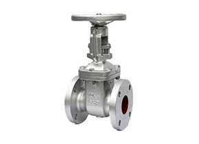
1. Gate Valves
Description & Working Principle:
Gate valves are linear-motion isolation valves designed to start or stop fluid flow completely. They operate by lifting a rectangular or wedge-shaped gate out of the flow path using a threaded stem and handwheel. When fully open, the gate retracts entirely into the bonnet, providing an unobstructed flow path with minimal pressure drop. In the closed position, the gate seats firmly against two parallel or angled sealing surfaces, creating a tight metal-to-metal seal. These valves are multi-turn devices, requiring several rotations to transition between open and closed states. Their straight-through design makes them unsuitable for throttling, as partial opening causes high-velocity flow that can erode seats and gates.
Key Features:
- Full-bore design – Minimal flow restriction when fully open
- Bi-directional sealing – Can block flow from either direction
- Slow operation – Requires multiple turns to open/close
- Metal-seated construction – Suitable for high-temperature applications
- Not for throttling – Partial opening damages seats
- Rising or non-rising stem options for position indication
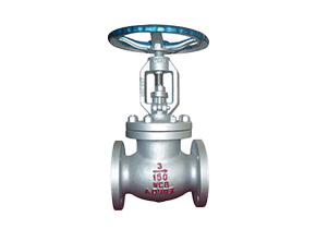
2. Globe Valves
Description & Working Principle:
Globe valves are primarily used for flow regulation and throttling in oil and gas systems. They feature a spherical body with an internal baffle that forces fluid to change direction twice, creating resistance for better flow control. A disc or plug attached to a vertical stem moves perpendicular to the seat, allowing precise adjustment of the flow area. The screw-down handwheel mechanism enables fine control, with each turn incrementally changing the disc position. Unlike gate valves, globe valves create significant pressure drops due to their tortuous flow path. They provide excellent shutoff capability, with various disc designs (plug, ball, or composition) available for different service conditions.
Key Features:
- Precise throttling – Excellent flow control capability
- High-pressure containment – Robust design for severe service
- Multiple disc options – Plug, ball, or composition discs
- Higher pressure drop – Due to flow direction changes
- Visual stem indication – Rising stem shows valve position
- Repairable seats – Many designs allow seat replacement
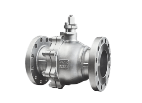
3. Ball Valves
Description & Working Principle:
Ball valves provide quick quarter-turn on/off control using a rotating ball with a cylindrical bore. When the handle aligns the bore with the pipeline, fluid flows unimpeded. A 90° turn positions the solid portion of the ball across the flow path, blocking fluid completely. The seats (typically PTFE or metal) create bubble-tight seals against the ball surface. Ball valves are classified by mounting style (floating or trunnion) and bore type (full or reduced port). Floating ball designs suit smaller sizes, while trunnion-mounted balls handle high pressures.
Key Features:
- Quarter-turn operation – Fast opening/closing
- Low torque requirement – Easy to automate
- Bubble-tight shutoff– Excellent sealing performance
- Full-port options – Minimal pressure drop
- Fire-safe designs – Available for critical services
- Minimal maintenance – Few moving parts
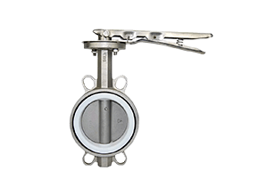
4. Butterfly Valves
Description & Working Principle:
Butterfly valves regulate flow using a thin, circular disc mounted on a rotating shaft. When open, the disc parallels the flow direction, creating minimal obstruction. A 90° rotation positions the disc perpendicular to flow, blocking passage completely. Concentric designs place the shaft at the disc centerline, while high-performance triple-offset versions position the shaft eccentrically for tighter seals. Resilient-seated versions use elastomer linings, while metal-seated designs handle higher temperatures.
Key Features:
- Compact & lightweight – Ideal for large pipe sizes
- Low-pressure drop – When fully open
- Quarter-turn operation – Rapid actuation
- Cost-effective – Cheaper than gate valves for large diameters
- Limited throttling capability – Except high-performance designs
- Wafer/lug body styles – Different installation options
5. Check Valves
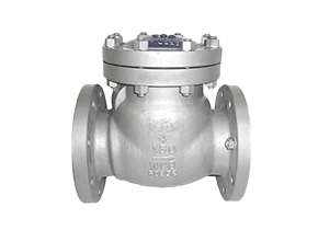
Description & Working Principle:
Check valves automatically prevent backflow by allowing fluid to move in only one direction. They operate without external control—forward pressure pushes the closure element (swing disc, lift piston, or dual plates) open, while reverse flow or gravity forces it closed. Swing check valves use a hinged disc that swings away from the seat, while lift checks employ a piston-like disc that moves vertically. Dual-plate wafer checks feature two spring-loaded half-discs that minimize water hammer.
Key Features:
- Self-actuating – No manual operation required
- Various designs – Swing, lift, dual-plate, ball check
- Critical for pump protection – Prevents reverse rotation
- Installation orientation sensitive – Must match flow direction
- Cracking pressure consideration – Minimum pressure to open
- Slam prevention – Some designs cushion closing
6. Plug Valves
Description & Working Principle:
Plug valves control flow through a cylindrical or tapered plug with a port that aligns with the pipeline. Quarter-turn rotation switches between open (port aligned) and closed (solid section blocking flow) positions. Lubricated versions use grease to seal between plug and body, while non-lubricated types employ elastomeric sleeves. The full-port design offers minimal flow restriction, while multi-port versions enable flow diversion.
Key Features:
- Quarter-turn operation – Quick open/close
- Excellent for slurries – Resists clogging
- Lubricated or non-lubricated – Service-specific designs
- Multi-port configurations – Flow diversion capability
- Bubble-tight shutoff – When properly maintained
- High-temperature capability – Metal-seated versions
7. Control Valves
Description & Working Principle:
Control valves automatically regulate flow in response to signals from process control systems. They consist of a valve body, actuator, and positioner that precisely positions the trim (plug, ball, or disc) to maintain desired flow rates. Globe-style bodies are common for throttling, while rotary designs (ball, butterfly) suit high-capacity applications. The positioner compares the control signal to the actual valve position and adjusts accordingly.
Key Features:
- Process automation – Integral to control loops
- Various actuator types – Pneumatic, electric, hydraulic
- Characterized trim – For specific flow characteristics
- Position feedback – For precise control
- High-rangeability options – For wide flow variations
- Smart capabilities – Digital communication in modern valves
8. Pressure Relief Valves
Description & Working Principle:
Pressure relief valves automatically protect systems from overpressure by opening at a preset value and reclosing when normal pressure resumes. Spring-loaded designs use adjustable compression springs to set the opening pressure. When system pressure overcomes spring force, the disc lifts, allowing fluid to escape. Pilot-operated versions use system pressure to control a smaller pilot valve that manages the main valve operation.
Key Features:
- Critical safety devices – Prevent equipment failure
- Adjustable set pressure – Field-configurable in some designs
- Reclosing capability – Unlike rupture discs
- Various designs – Spring-loaded, pilot-operated
- ASME code compliance – Required for most applications
- Regular testing needed – To ensure proper operation
9. Solenoid Valves
Description & Working Principle:
Solenoid valves are electromechanically operated valves that control fluid flow using an electromagnetic solenoid coil. When energized, the coil generates a magnetic field that moves a plunger or armature, either opening or closing the valve orifice. These valves provide rapid on/off control and are commonly used in automated fluid systems. They operate in two main configurations: direct-acting (where the solenoid directly opens the orifice) and pilot-operated (using system pressure to assist in opening a larger main valve). Solenoid valves can be normally closed (NC) (default closed, opens when energized) or normally open (NO) (default open, closes when energized). They are widely used in applications requiring remote or automated flow control, such as fuel systems, lubrication systems, and pneumatic circuits.
Key Features:
- Fast response time – Instantaneous opening/closing (milliseconds)
- Low power consumption – Energy-efficient operation
- Compact and lightweight – Easy to integrate into systems
- Wide range of materials– Brass, stainless steel, or plastic bodies
- Multiple voltage options – AC/DC, 12V, 24V, 110V, 220V
- Variety of port sizes – From 1/8″ to 2″ for different flow rates
- Explosion-proof options – For hazardous environments
- Manual override available – For emergency operation
Types of Solenoid Valves
Direct-Acting Solenoid Valves
– Operate without relying on system pressure
– Suitable for low-pressure or vacuum applications
– Simple design with fewer moving parts
Pilot-Operated Solenoid Valves
– Use system pressure to assist in opening/closing
– Ideal for high-flow or high-pressure applications
– Require a minimum pressure differential to function
2-Way, 3-Way, and 4-Way Solenoid Valves
– 2-Way: Basic on/off control (inlet and outlet)
– 3-Way: Diverts flow between two outlets (common in pneumatic systems)
– 4-Way: Used for double-acting cylinders (forward/reverse control)
Criteria for Valve Selection
This guide outlines the essential considerations that flow application engineers should follow when systematically choosing valves and flow control devices for thermodynamic systems. The aim is to provide a logical sequence of key parameters for effective decision-making.
The current market offers a vast array of valves and flow control products from numerous brands and manufacturers, each with unique features. This wide selection allows engineers to choose the most suitable option for various system designs. In addition to technical factors, engineers must also weigh commercial and logistical aspects such as cost, lead time, shipping, maintenance needs, and compliance with regulations.
1. Determining Valve Function Based on Application
The initial step in valve selection is to define the intended purpose within the system. This leads to categorizing valves by their specific functions:
- Shut-off (Isolation): Used to completely stop fluid flow when required.
- Non-return (Check): Prevents reverse flow when pressure drops or is lost.
- Flow Regulation (Throttling): Allows adjustment of flow rate, diversion, mixing, or remote operation.
- Safety: Protects equipment and personnel by relieving excess pressure in vessels.
- Air Release and Surge Protection: Especially in water systems, these valves vent trapped air and prevent pressure surges that could damage pipelines.
- Steam Traps: Remove condensate from steam systems, maintaining efficient heat transfer.
2. Assessing Valve Pressure Rating
The next consideration is to establish the appropriate pressure rating for the valve, which depends on the system’s maximum operating pressure and temperature. Reference should be made to standardized pressure classes such as DIN (PN ratings) and ANSI (Class ratings), for example:
| DIN (PN) | ANSI (Class) |
|---|---|
| PN 10 | Class 125 |
| PN 16 | Class 150 |
| PN 25 | Class 300 |
| PN 40 | Class 600 |
| PN 64 | Class 900 |
| PN 100 | Class 1500 |
| PN 250 | Class 2500 |
It is important to note that the maximum allowable working pressure decreases as temperature increases. Always consult pressure/temperature charts provided by manufacturers.
3. Selecting Valve Materials
After determining the pressure rating, select materials for the valve’s components based on compatibility with the process fluid, resistance to corrosion and abrasion, and temperature limits. Consider the following:
- Pressure-containing parts: Body and bonnet, which must be compatible with the process fluid.
- Sealing elements: Gaskets and packing must withstand the fluid’s temperature and chemical properties.
- Fasteners and coatings: Should be chosen for durability, especially in corrosive or outdoor environments.
Material selection must also account for factors such as fluid velocity, presence of solids, and extreme temperatures. For instance, high-alloy steels may be needed for elevated temperatures, while rubber linings are suitable for abrasive slurries. Manufacturer guidelines for temperature limits on soft goods (e.g., NBR seals) should always be followed.
4. Choosing the Valve Actuation Method
Valves can be operated in several ways:
- Manual: By handwheel or lever.
- Self-actuated: Using the process fluid’s own pressure.
- Powered: Electrically, pneumatically, or hydraulically.
The choice of actuation depends on factors such as accessibility, frequency of operation, power availability, and the required level of control or automation.
5. Sizing the Valve
Valve sizing is standardized according to nominal diameter, following international standards. The correct size is determined by factors like flow rate, pressure drop, and the potential for cavitation. Accurate sizing ensures optimal system performance and longevity.
6. Economic and Practical Considerations
Finally, the engineer must balance technical requirements with economic factors and market trends. While high-specification materials and designs may offer maximum reliability, they may not always be economically justified. The selection process should integrate technical suitability with cost-effectiveness, availability, and maintenance needs.
Selecting the right valve is a complex task that requires careful evaluation of technical parameters alongside practical and economic considerations. Engineers, plant operators, contractors, and suppliers must collaborate to ensure the chosen valve meets all operational and safety requirements within budgetary constraints.