What is a Distributed Control System (DCS)?
A Distributed Control System (DCS) is an advanced automated control system used extensively in industrial and process plants. Unlike centralized control systems, a DCS distributes control functions across multiple autonomous controllers within the plant, allowing localized control while maintaining centralized monitoring and coordination.
DCS systems are widely used in industries such as oil and gas, chemical, power generation, and water treatment due to their reliability, scalability, and integration capabilities.
Key Components of a DCS
- Engineering Workstation (EWS): Used for configuration, programming, and system diagnostics.
- Operator Workstation (OWS): Provides Human-Machine Interface (HMI) for monitoring and control.
- Controllers: Process control units placed close to the plant sections to manage real-time control.
- Input/Output Modules (I/O): Interface between field devices and controllers.
- Communication Network: Ethernet, Fieldbus, or proprietary networks used for internal communication.
- Field Devices: Sensors, transmitters, actuators, and valves connected to the system for process interaction.
Example: A temperature transmitter sends data to the controller via an analog I/O module. The controller processes the signal and adjusts a control valve accordingly.
How the DCS System Works
- Sensors collect process data (temperature, pressure, flow, etc.).
- Data is transmitted to local controllers through I/O modules.
- Controllers process the data based on logic or PID loops.
- Output commands are sent to actuators or valves.
- Operators monitor and adjust operations via the HMI.
- Data is logged and alarms generated if limits are breached.
DCS Architecture
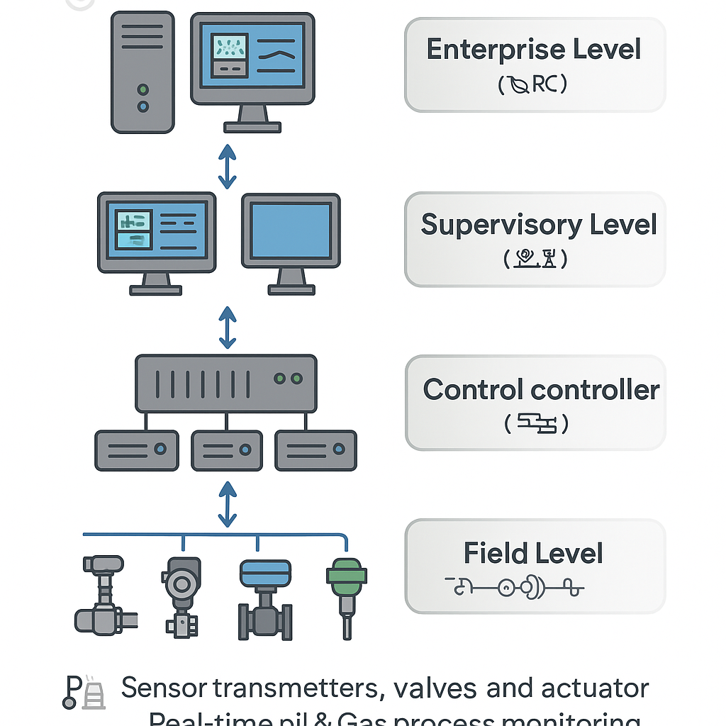
DCS follows a hierarchical structure with multiple layers:
- Field Level: Field instruments and actuators.
- Control Level: Distributed controllers with dedicated control logic.
- Supervisory Level: Operator and engineering stations with visualization and logging.
- Enterprise Level: Integration with management and ERP systems.
Communication in DCS
- Common protocols: MODBUS, PROFIBUS, HART, FOUNDATION Fieldbus.
- Redundant communication lines ensure system reliability.
- Use of deterministic networks ensures timely control actions.
Advantages of DCS
- High reliability due to redundancy.
- Improved process stability through precise control.
- Easy troubleshooting with diagnostic tools.
- Better scalability for plant expansion.
- Integration with safety systems and MES/ERP layers.
Limitations of DCS
- High initial cost of setup and hardware.
- Complex configuration and maintenance.
- Vendor lock-in risks due to proprietary systems.
- Requires skilled personnel for programming and diagnostics.
Comparison with PLC and SCADA
| Feature | DCS | PLC | SCADA |
|---|---|---|---|
| Primary Use | Continuous process control | Discrete control | Supervisory monitoring |
| Scalability | High | Medium | High |
| Redundancy | Built-in | Optional | Optional |
| Architecture | Distributed | Centralized | Distributed |
| Operator Interface | HMI with alarms/trends | Basic HMI | Advanced HMI/Database |
Key Components in a DCS Signal Path
Here’s a breakdown of all the key components that help a field instrument (like a sensor) communicate with the DCS system, from the field to the control room:
1. Field Instruments
Field Instruments are the devices that measure (sensors) or control (actuators) the process.
Examples:
- Sensors: Pressure transmitters, temperature sensors (RTDs/thermocouples), flow meters.
- Actuators: Control valves, motor starters, solenoid valves.
Function:
- Converts physical parameters (pressure, temperature) into electrical signals (4-20 mA, digital HART/Fieldbus).
- Example: A pressure transmitter sends 12 mA to represent 50 psi.
2. Junction Box (JB)
A junction box is a weatherproof enclosure where field wiring terminates before going to the control system.
Why Needed?
- Groups multiple field cables (e.g., 10 temperature sensors in one area).
- Simplifies wiring (instead of running each sensor’s wire all the way to the control room).
- Protects connections from dust, water, and damage.
How It Works?
- Each sensor wire connects to terminals inside the JB.
- From the JB, a **multi-core cable** carries all signals to the marshalling cabinet.
3. Marshalling Cabinet (MC)
Marshalling Cabinet is a cabinet where field wiring is organized and interfaced with the DCS.
Why Needed?
- Acts as a middleman between field instruments and the DCS.
- Provides termination points, surge protection, and signal conditioning.
Key Parts Inside:
- Terminal Blocks – Where field wires connect.
- Signal Isolators– Protects DCS from electrical noise.
- Surge Protectors – Prevents lightning/voltage spikes from damaging the system.
How It Works?
1. Field wires from junction boxes enter the marshalling cabinet.
2. Wires are terminated neatly on terminal blocks.
3. Signals are isolated/converted if needed (e.g., 4-20 mA to digital).
4. Signals are sent to the **DCS I/O cards.
4. I/O Cards (Input/Output Cards)
The DCS hardware that reads sensor signals and sends commands to actuators.
Types:
- Analog Input (AI) – Reads 4-20 mA signals (e.g., pressure, temperature).
- Digital Input (DI) – Reads ON/OFF signals (e.g., pump running/stopped).
- Analog Output (AO) – Sends 4-20 mA to control valves.
- Digital Output (DO)– Sends ON/OFF to motors/solenoids.
Function:
- Converts raw signals into digital data the DCS can understand.
- Example: A 12 mA signal from a pressure transmitter → DCS reads it as 50.0 psi.
5. DCS Controller
The brain that processes data and makes control decisions.
How It Works?
- Receives data from I/O cards.
- Runs control logic (e.g., PID loops, alarms).
- Example: If pressure > 60 psi → Trigger alarm, open relief valve.
6. Operator Workstation (HMI – Human Machine Interface)
The computer screen where operators monitor and control the plant.
Displays:
- Live process values (e.g., pressure, temperature).
- Alarms (e.g., “High Pressure in Pipeline!”).
- Trends (historical data graphs).
Operator Actions:
- Can manually override automatic controls.
- Acknowledges alarms.
7. Historian (Data Storage)
A database that stores all process data for reports and analysis.
Why Needed?
- Tracks past performance (e.g., “Why did pressure spike last Tuesday?”).
- Helps in optimization and troubleshooting.
Full Signal Path Summary
1. Field Instrument (e.g., pressure transmitter) measures data → sends **4-20 mA signal.
2. Junction Box collects multiple field signals → sends via multi-core cable.
3. Marshalling Cabinet organizes wiring → provides isolation/surge protection.
4. I/O Cards convert signals → sends to DCS Controller.
5. DCS Controller processes data → sends to HMI for operators.
6. Historian records all data for future analysis.